


ANALYSIS BY STAAD-PRO AND DESIGN OF STRUCTURAL ELEMENTS BY MATLAB

1B.E., MTech (Civil Engineering), Assistant Professor, Department of Civil Engineering, Professor Ram MegheCollege of Engg & Management, Amravati, India
ABSTRACT
The analysis and design of multi storey building is carried out usually in the software packages which are very strong in analysis. The different software like STAAD-PRO, Etabs, etc is used for such purposes. The programming tools like C+, JAVA, etc are also used in many structural elements for different methods of calculations. The high level programming tools like MATLAB is used for many complicated problems in various fields. In the present paper the STAAD-PRO is used for the purpose of analysis and design of a building. The building was analyzed for the seismic behavior. Shear force, bending moment, deflections are calculated using the software, the reinforcement details are also available through the design. The coding of STAAD editor is also included in this paper. The design of slab, beam, column and footing are carried out by the programming of MATLAB. The objective of this study was to check the programming language for these structural elements.
© 2017 AESS Publications. All Rights Reserved.
Keywords: STAAD-PRO, MATLAB, Beams, columns, Shear force, Bending moment, Deflection, Programming.
Article History: Received: 26 April 2017, Revised: 25 May 2017, Accepted: 30 May 2017, Published: 2 June 2017
Contribution/ Originality: This study contributes in the existing literature that MATLAB program and STAAD editor files is provided. The flowchart of the program is also provided. The results of the STAAD is provided in graphs.
1. INTRODUCTION
For high performance numerical computation and visualization MATLAB is a good software with high level programming language [1]. The formulation and obtaining the solution for the minimum cost design for bridge superstructure and for this the high level programming language i.e. MATLAB is used [2]. The finite element approach is used for analysis of dam in which time history method is used to study the dynamic behavior. The gravity dam for earthquake analysis was studied by STAAD-PRO in the investigation [3].
STAAD-PRO and Etabs are the software which are used for the multi storied buildings. Shear force, bending moments, reinforcement and deflection are the parameters found out after analysis and design is carried out [4]. Most engineering software tools use typical menu-based user interfaces, and they may not be suitable for learning tools because the solution processes are hidden and students can only see the results. An educational tool for simple beam analyses is developed using a pen based user interface with a computer so students can write and sketch by hand. The geometry of beam sections is sketched, and a shape matching technique is used to recognize the sketch [5]. The structural analysis and design of the structural frame considered was done using the STAAD-Pro software which is very user friendly and effective. First a typical frame is selected from the structure.
The frame was analyzed and designed according to the PEB concept and then by the CSB concepts [6].
The power tool for Computerized Structural engineering STAAD. Pro is the most popular structural engineering software product for 3D model generation, analysis and multi-material design. It has an intuitive, user-friendly, visualization tools, powerful analysis and design facilities and seamless integration to several other modeling and design software products [7]. The seismic design of steel frame is carried out by the STAAD-PRO. RCC frame and steel frame is compared by analyzing in the STAAD-PRO [8]. The modeling and analysis of aqueduct structure is carried out by STAAD-PRO. Seismic static loading is applied on the aqueduct in terms of self weight and other types loading [9]. Computer aided design of a twin reinforced concrete multi-storey tower is presented in this work and it entails the use of Midas Gen software for modeling, analyzing and designing of a 25 storey twin tower and comparing the results with STAAD Pro software
and manual design [10]. A study of one R.C. buildings, of G + 2 storey institutional building (designed according to IS 456:2000) are analyzed. Analysis and redesigning by changing the main reinforcement of various frame elements and again analyzing [11]. RC –Design suite is a reinforced concrete design program that has numerous applications for the design of concrete structures. It contains modules for the design of beams, columns, footings and slabs. For this project the students utilized this program only for the design of floor slab and combined footings. Design of beams and columns are carried out in STAAD- III package itself [12].
Seventy nine soil samples were collected from three different sites in Iraq (Mosul, Baghdad and Basrah) to investigate their effect on the foundation of the buildings. The results of the tests were used in a hypothetical building and analyzed by STAAD Pro.v8i model. Soil in Mosul region includes many types such as clayey (expansive clayey), gypsum and silty clay. The results indicated that the bearing pressure under the foundation was lower than that calculated. Similar results were obtained when using the relatively worse bearing pressure values [13]. A research presents the dynamic time history analysis and response spectrum method of a concrete gravity dam by using STAAD-PRO. Here Finite Element Approach is used to analyze the dam. A concrete gravity dam model is prepared in STAAD-PRO to perform the time history analysis and response spectrum analysis and a comparison is done between both these methods [14].
2. METHODOLOGY
A research presents the main features and organization of STAADPRO, a computer program that has been developed for the static and seismic stability evaluations of concrete gravity dams. STAADPRO is based on the gravity method using rigid body equilibrium and beam theory to perform stress analyses, compute crack lengths, and safety factors. Seismic analyses could be done using either the pseudo-static or a simplified response spectrum method [15]. The Curtain Wall is designed using STAADPRO to resist and handle all the imposed loads on it as well as keep air and water from penetrating in the building. The loads imposed on the curtain wall are transferred to the building structure through structural interface (i.e. brackets) which attaches the mullions to the building [16].
The main aim of a research is to study which section of the large span cantilever structures are more safe and economical among the three sections of pipe, angle and tube. On the study the inference is that by comparing the output of STAAD.Pro (structural analysis and design) analysis results of different sections and it is concluded that the steel take off for pipe section is 3% less than tube section in weight and 14% less than angle section in weight [17]. A six storey RC building in zone III on medium soil is analyzed using the software STAAD – PRO. It is assumed that no parking floor for the building. Seismic analysis is performed using Equivalent lateral force method given in IS 1893:2002 and also by dynamic analysis [18].
The analysis and design of a building is carried out in STAAD-PRO for the following data:
Floor to floor height for ground floor = 3.4m
Floor to floor height for above floors = 4m
Plinth height = 0.6m
Depth of foundation below ground level = 1.8m
Thickness of slab at each floor = 0.125m
External wall thickness = 0.23m
Internal wall thickness = 0.15m
Sizes of column = 450 x 600
Sizes of beam = 230 x 380
Live load on floors = 3kN/m2 (for earthquake 25% of live load)
Live load on roof = 3kN/m2 (for earthquake roof live load = 0)
Floor finish = 0.75kN/m2
Roof treatment = 0.75kN/m2
Site location at seismic zone = III
Building resting on = medium soil
Density of wall = 20kN/m2
Density of concrete =25kN/m2
Grade of concrete = 25N/mm2
Grade of steel = 415N/mm2 (main reinforcement)
Grade of steel = 250N/mm2 (secondary reinforcement)
Dead load
External member load for ground floor = (0.23 x 1 x 1) x 20 x (4 – 0.38)
Internal member load for ground floor = (0.15 x 1 x 1) x 20 x (4 – 0.6 – 0.38)
For first floor and above
External member load = (0.23 x 1 x 1) x 20 (4 – 0.38)
Internal member load = (0.75 x 1 x 1) x 20 (4-0.38)
Parapet load = 0.23 x 1 x 1 x 20
Floor Dead load = 1 x [125 + 75 / 1000] x 1 = 5kN/m2
2.1. STAAD-PRO Input File
The analysis and design of a structure considering earthquake resistance parameters is carried out in STAAD-PRO by the coding as detailed in the Appendix-A. This program gives in detail about the analysis of structure including the load conditions and combinations, design of structure by IS code method & earthquake provisions are included.
3. MATLAB PROGRAMMING
Matlab is a very useful CAE tool for numerical analysis. In the dissertation, the computational algorithms for several vibration control systems are implemented with Matlab and used for diverse simulation studies. Matlab has many embedded tools which simplify matrix operations encountered in the vibration control [19].
One of the interesting engineering application is space truss, a three dimensional element, particularly used as roof for industrial and commercial structure spanning large distances. Analysis of space truss can be performed by much commercial FEA software available in the market. A research concerns the current growth of MATLAB based program which analyze the space truss step by step as done in Finite Element Analysis [20].
The MATLAB programming for footing, column, beam and slab is completed once the analysis in STAAD-PRO is done.
3.1. Design of Footing
Problem: Design a rectangular footing of uniform thickness bearing a vertical load of 1616 kN having a base size of 230 mm X 600 mm. Assuming safe bearing capacity of soil is 150 kN/m2. Using M25 grade of concrete and Fes 415 steel.
The programming in MATLAB is detailed in Appendix-B giving all the commands and syntax to design the footing so that any design can take place accordingly.
3.2. Design of Column
Problem: Design a column size of 450 mm X 600 mm subjected to an axial load of 2500 kN under the service dead load and live load. The column has an unsupported length of 4 m and effectively held in position in both ends. Using M25 grade of concrete and Fes 415 steel. The programming in MATLAB is detailed in Appendix-C giving all the commands and syntax to design the column so that any design can take place accordingly.
3.3. Design of Beam
Problem: Design a rectangular beam for simply supported span of 4m subjected to superimposed ultimate load of 41.11 kN/m and size of beam is limited to 230 mm X 380 mm. Use of M25 grade of concrete and Fe415 grade of steel. The programming in MATLAB is detailed in Appendix-D giving all the commands and syntax to design the beam so that any design can take place accordingly.
3.4. Design of Slab
Problem: Design of a two way continuous slab is subjected to uniformly distributed load of 3 kN/m2 for a room size of 4 m X 4 m. Use of M25 grade of concrete and Fe415 grade of steel. The programming in MATLAB is detailed in Appendix-E giving all the commands and syntax to design the slab so that any design can take place accordingly.
4. RESULTS & DISCUSSION
The following graphs show the results in terms of deflection, shear force and moment of the beams on First, second, third, fourth floor and fifth floor.
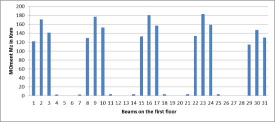
Graph-No.1. Moments (Mz) for the beams on first floor
From the above graph it is clear that the maximum moment in the beam is 182 kNm in case of beam on the first floor while the minimum moment is noted to be 0.5 kNm in the Z direction of beam locally.
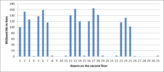
Graph-No.2. Moments (Mz) for the beams on second floor
From the above graph it is clear that the maximum moment in the beam on the second floor found to be 162 kNm which is lower than the moment on the beam of second floor while the minimum moment on the beam of second floor found to be 0.5 kNm in most of the beams.
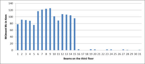
Graph-No.3. Moments (Mz) for the beams on third floor
From the above graph it is clear that the moment in the beams of third floor is 122 kNm which is lower than the moment on the beams of first and second floor while the minimum moment is observed to be 0.25 kNm.
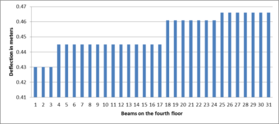
Graph-No.4. Deflection for the beams on fourth floor
From the above graph it is clear that the maximum deflection on the fourth floor found to be 0.465 m and it is more than the deflections of first and second floor while the minimum deflection found to be 0.43 m in other beams.
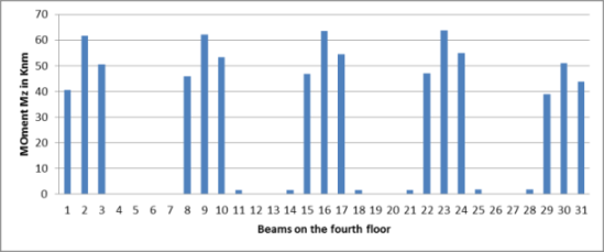
Graph-No.5. Moments (Mz) for the beams on fourth floor
The beams on the fourth floor have lower moments than that of first, second and third floor and maximum moment found to be 65 kNm while other beams have moment of 0.1 kNm and it is clear that the moment on the beams are decreases as the height of floor increases.
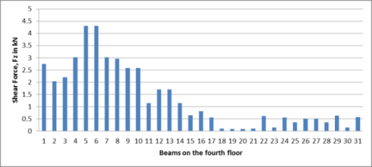
Graph-No. 6. Shear Force (Fz) for the beams on fourth floor
The shear force on the beams on fourth floor found to be maximum as 4.25 kN in the Z direction locally while the minimum shear force is 0.1 kN in other beams of fourth floor.
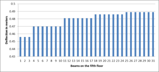
Graph-No.7. Deflection for the beams on fifth floor
The deflection on the highest floor is maximum i.e 0.488 and it is higher than the deflections of first, second, third and fourth floor while the minimum deflection found to be 0.455.
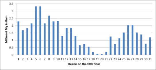
Graph-No.8. Moments (My) for the beams on fifth floor
The moments on the fifth floor in Y direction is found to be 3.25 kNm and observed that the moment on the top floor as 3.25 kNm which is much lower than the moments on the remaining floors.

Graph-No. 9. Shear Force (Fz) for the beams on fifth floor
The shear force on top floor i.e fifth floor found to be 3.25 kN which is also lower than that of on the remaining floors.
5. ADVANTAGES & LIMITATIONS
The advantage of the present work includes programming code of design members of structures like beam, slab, column and footing. Most of the cases the design is carried out on the MS-Excel sheet but the programming in MATLAB are also a good option. The present paper also discusses the STAAD-PRO programming part which also not detailed in other work and earthquake resistant design is also given in that part.
The limitations of the present work involves programming in only one language, other languages need to checked for more faster results. Also design and analysis is carried out in STAAD-PRO, other software tools need to be checked for faster results. Also reinforcement detailing is not provided.
6. CONCLUSION
The analysis and design of a structure in STAAD-PRO software is completed, the maximum shear force and bending moment in the column, beam and slab is noted. The noted values are programmed in MATLAB software so that the required area of reinforcement and size for footing, column, beam and slab is properly designed. The advantages of user friendly software like STAAD-PRO for analysis and MATLAB programming for the design of structural elements are found out.
| Funding: This study received no specific financial support. |
| Competing Interests: The author declares that there are no conflicts of interests regarding the publication of this paper. |
REFERENCES
[1] S. P. Nirkhe, D. N. Kakade, and A. G. Dahake, "Design of flat slab with matlab," International Journal of Engineering Research, vol. 5, pp. 537-540, 2016.
[2] K. Rajesh, N. G. Gore, and P. J. Salunke, "Applications of matlab in optimization of bridge superstructure," International Journal of Research in Engineering and Technology, vol. 3, pp. 34-39, 2014.
[3] A. B. Rampure and M. Mangulkar, "Finite element analysis of concrete gravity dam by using STAAD-PRO," International Journal of Engineering Research, vol. 5, pp. 549-554, 2016.
[4] D. Ramya and K. A. V. Sai, "Comparative study on design and analysis of multistory building (G+10) by STAAD-PRO software and Etabs software," International Journal of Engineering Science and Research Technology, vol. 4, pp. 125-130, 2015.
[5] S. S. Yong, "Development of educational software for beam loading analysis using pen-based user interfaces," Journal of Computational Design and Engineering, vol. 1, pp. 67-77, 2014. View at Google Scholar | View at Publisher
[6] C. M. Meera, "Pre-engineered building design of an industrial warehouse," International Journal of Engineering Science and Emerging Technologies, vol. 5, pp. 75-82, 2013. View at Google Scholar
[7] F. Syed, C. K. B. Sarath, and R. S. Kanakambara, "Design concept of pre engineered building," International Journal of Engineering Research and Applications, vol. 2, pp. 267-272, 2012. View at Google Scholar
[8] S. M. Dhawade and P. S. Pajgade, "Consideration of seismic design of multistoried steel structure," International Journal of Civil Engineering Research, vol. 5, pp. 177-182, 2014.
[9] S. Naveen, C. R. Zalakkumar, and P. A. Pratik, "Modeling and analysis of aqueduct using STAAD-PRO," International Journal of Engineering and Technology, vol. 3, pp. 2324-2329, 2016.
[10] S. A. Raji, O. F. Ajala, and S. E. Ayenigba, "Computer aided design of a twin reinforced concrete multi storey tower," Journal of Multidisciplinary Engineering Science and Technology, vol. 3, pp. 4584-4588, 2016.
[11] S. Aakash and S. S. Kushwah, "Static analysis of G+2 institutional building in Bhopal," International Journal of Engineering Research and Applications, vol. 5, pp. 159-167, 2015.
[12] P. Jayachandran and S. Rajasekaran, "Structural design of multi-story residential building for Salem, India," presented at the ASEE Conference at WPI, 2016.
[13] A.-T. Entidhar, A.-A. Nadhir, and K. Sven, "Effect of bearing capacity on designing foundations in Iraq using STAAD-PRO v8i," Scientific Research Journal, vol. 6, pp. 292-303, 2014. View at Google Scholar | View at Publisher
[14] B. R. Aarti and N. M. Madhuri, "Comparison between response spectrum and time history method of dynamic analysis of concrete gravity dam," Open Journal of Civil Engineering, vol. 6, pp. 329-334, 2016. View at Google Scholar | View at Publisher
[15] T. Subramani and D. Ponnuvel, "Seismic and stability analysis of gravity dams using STAAD-PRO," International Journal of Engineering Research and Development, vol. 1, pp. 44-54, 2012. View at Google Scholar
[16] T. Pallavi and S. Santosh, "Structural design of a glass facade," International Journal of Scientific and Research Publications, vol. 5, pp. 1-6, 2015.
[17] P. Abhilash and R. K. S. Ramayanapu, "Studied on large span cantilever structures by using STAAD-PRO analysis," International Journal of Engineering Science and Research Technology, vol. 3, pp. 90-96, 2014.
[18] T. Subramani, B. Saravanan, and J. Jayalakshmi, "Dynamic analysis of flanged shear wall using STAAD-PRO," International Journal of Engineering Research and Applications, vol. 4, pp. 150-155, 2014. View at Google Scholar
[19] M. C. Yi-Mei, "Computer-aided engineering methodology for structural optimization and control," Dissertation of Master of Engineering in Civil and Environmental Engineering, MIT, USA, 2000.
[20] P. Sangeetha, K. P. Naveen, and R. Senthil, "Finite element analysis ofspace truss using matlab," ARPN Journal of Engineering and Applied Sciences, vol. 10, pp. 3812-3816, 2015.
Appendix A (STADD-Programme)
STAAD SPACE
START JOB INFORMATION
ENGINEER DATE 15-Apr-15
END JOB INFORMATION
INPUT WIDTH 79
UNIT METER KN
JOINT COORDINATES
1 0 0 0; 2 4 0 0; 3 8 0 0; 4 12 0 0; 5 0 0 4; 6 4 0 4; 7 8 0 4; 8 12 0 4;
9 0 0 8; 10 4 0 8; 11 8 0 8; 12 12 0 8; 13 0 0 12; 14 4 0 12; 15 8 0 12;
16 12 0 12; 17 0 0 16; 18 4 0 16; 19 8 0 16; 20 12 0 16; 21 0 1.8 0;
22 4 1.8 0; 23 8 1.8 0; 24 12 1.8 0; 25 0 1.8 4; 26 4 1.8 4; 27 8 1.8 4;
28 12 1.8 4; 29 0 1.8 8; 30 4 1.8 8; 31 8 1.8 8; 32 12 1.8 8; 33 0 1.8 12;
34 4 1.8 12; 35 8 1.8 12; 36 12 1.8 12; 37 0 1.8 16; 38 4 1.8 16; 39 8 1.8 16;
40 12 1.8 16; 41 0 5.8 0; 42 4 5.8 0; 43 8 5.8 0; 44 12 5.8 0; 45 0 5.8 4;
46 4 5.8 4; 47 8 5.8 4; 48 12 5.8 4; 49 0 5.8 8; 50 4 5.8 8; 51 8 5.8 8;
52 12 5.8 8; 53 0 5.8 12; 54 4 5.8 12; 55 8 5.8 12; 56 12 5.8 12; 57 0 5.8 16;
58 4 5.8 16; 59 8 5.8 16; 60 12 5.8 16; 61 0 9.8 0; 62 4 9.8 0; 63 8 9.8 0;
64 12 9.8 0; 65 0 9.8 4; 66 4 9.8 4; 67 8 9.8 4; 68 12 9.8 4; 69 0 9.8 8;
70 4 9.8 8; 71 8 9.8 8; 72 12 9.8 8; 73 0 9.8 12; 74 4 9.8 12; 75 8 9.8 12;
76 12 9.8 12; 77 0 9.8 16; 78 4 9.8 16; 79 8 9.8 16; 80 12 9.8 16; 81 0 13.8 0;
82 4 13.8 0; 83 8 13.8 0; 84 12 13.8 0; 85 0 13.8 4; 86 4 13.8 4; 87 8 13.8 4;
88 12 13.8 4; 89 0 13.8 8; 90 4 13.8 8; 91 8 13.8 8; 92 12 13.8 8;
93 0 13.8 12; 94 4 13.8 12; 95 8 13.8 12; 96 12 13.8 12; 97 0 13.8 16;
98 4 13.8 16; 99 8 13.8 16; 100 12 13.8 16; 101 0 17.8 0; 102 4 17.8 0;
103 8 17.8 0; 104 12 17.8 0; 105 0 17.8 4; 106 4 17.8 4; 107 8 17.8 4;
108 12 17.8 4; 109 0 17.8 8; 110 4 17.8 8; 111 8 17.8 8; 112 12 17.8 8;
113 0 17.8 12; 114 4 17.8 12; 115 8 17.8 12; 116 12 17.8 12; 117 0 17.8 16;
118 4 17.8 16; 119 8 17.8 16; 120 12 17.8 16; 121 0 21.8 0; 122 4 21.8 0;
123 8 21.8 0; 124 12 21.8 0; 125 0 21.8 4; 126 4 21.8 4; 127 8 21.8 4;
128 12 21.8 4; 129 0 21.8 8; 130 4 21.8 8; 131 8 21.8 8; 132 12 21.8 8;
133 0 21.8 12; 134 4 21.8 12; 135 8 21.8 12; 136 12 21.8 12; 137 0 21.8 16;
138 4 21.8 16; 139 8 21.8 16; 140 12 21.8 16;
MEMBER INCIDENCES
32 1 21; 33 2 22; 34 3 23; 35 4 24; 36 5 25; 37 6 26; 38 7 27; 39 8 28;
40 9 29; 41 10 30; 42 11 31; 43 12 32; 44 13 33; 45 14 34; 46 15 35; 47 16 36;
48 17 37; 49 18 38; 50 19 39; 51 20 40; 52 21 22; 53 22 23; 54 23 24; 55 21 25;
56 22 26; 57 23 27; 58 24 28; 59 25 26; 60 26 27; 61 27 28; 62 25 29; 63 26 30;
64 27 31; 65 28 32; 66 29 30; 67 30 31; 68 31 32; 69 29 33; 70 30 34; 71 31 35;
72 32 36; 73 33 34; 74 34 35; 75 35 36; 76 33 37; 77 34 38; 78 35 39; 79 36 40;
80 37 38; 81 38 39; 82 39 40; 83 21 41; 84 22 42; 85 23 43; 86 24 44; 87 25 45;
88 26 46; 89 27 47; 90 28 48; 91 29 49; 92 30 50; 93 31 51; 94 32 52; 95 33 53;
96 34 54; 97 35 55; 98 36 56; 99 37 57; 100 38 58; 101 39 59; 102 40 60;
103 41 42; 104 42 43; 105 43 44; 106 41 45; 107 42 46; 108 43 47; 109 44 48;
110 45 46; 111 46 47; 112 47 48; 113 45 49; 114 46 50; 115 47 51; 116 48 52;
117 49 50; 118 50 51; 119 51 52; 120 49 53; 121 50 54; 122 51 55; 123 52 56;
124 53 54; 125 54 55; 126 55 56; 127 53 57; 128 54 58; 129 55 59; 130 56 60;
131 57 58; 132 58 59; 133 59 60; 134 41 61; 135 42 62; 136 43 63; 137 44 64;
138 45 65; 139 46 66; 140 47 67; 141 48 68; 142 49 69; 143 50 70; 144 51 71;
145 52 72; 146 53 73; 147 54 74; 148 55 75; 149 56 76; 150 57 77; 151 58 78;
152 59 79; 153 60 80; 154 61 62; 155 62 63; 156 63 64; 157 61 65; 158 62 66;
159 63 67; 160 64 68; 161 65 66; 162 66 67; 163 67 68; 164 65 69; 165 66 70;
166 67 71; 167 68 72; 168 69 70; 169 70 71; 170 71 72; 171 69 73; 172 70 74;
173 71 75; 174 72 76; 175 73 74; 176 74 75; 177 75 76; 178 73 77; 179 74 78;
180 75 79; 181 76 80; 182 77 78; 183 78 79; 184 79 80; 185 61 81; 186 62 82;
187 63 83; 188 64 84; 189 65 85; 190 66 86; 191 67 87; 192 68 88; 193 69 89;
194 70 90; 195 71 91; 196 72 92; 197 73 93; 198 74 94; 199 75 95; 200 76 96;
201 77 97; 202 78 98; 203 79 99; 204 80 100; 205 81 82; 206 82 83; 207 83 84;
208 81 85; 209 82 86; 210 83 87; 211 84 88; 212 85 86; 213 86 87; 214 87 88;
215 85 89; 216 86 90; 217 87 91; 218 88 92; 219 89 90; 220 90 91; 221 91 92;
222 89 93; 223 90 94; 224 91 95; 225 92 96; 226 93 94; 227 94 95; 228 95 96;
229 93 97; 230 94 98; 231 95 99; 232 96 100; 233 97 98; 234 98 99; 235 99 100;
236 81 101; 237 82 102; 238 83 103; 239 84 104; 240 85 105; 241 86 106;
242 87 107; 243 88 108; 244 89 109; 245 90 110; 246 91 111; 247 92 112;
248 93 113; 249 94 114; 250 95 115; 251 96 116; 252 97 117; 253 98 118;
254 99 119; 255 100 120; 256 101 102; 257 102 103; 258 103 104; 259 101 105;
260 102 106; 261 103 107; 262 104 108; 263 105 106; 264 106 107; 265 107 108;
266 105 109; 267 106 110; 268 107 111; 269 108 112; 270 109 110; 271 110 111;
272 111 112; 273 109 113; 274 110 114; 275 111 115; 276 112 116; 277 113 114;
278 114 115; 279 115 116; 280 113 117; 281 114 118; 282 115 119; 283 116 120;
284 117 118; 285 118 119; 286 119 120; 287 101 121; 288 102 122; 289 103 123;
290 104 124; 291 105 125; 292 106 126; 293 107 127; 294 108 128; 295 109 129;
296 110 130; 297 111 131; 298 112 132; 299 113 133; 300 114 134; 301 115 135;
302 116 136; 303 117 137; 304 118 138; 305 119 139; 306 120 140; 307 121 122;
308 122 123; 309 123 124; 310 121 125; 311 122 126; 312 123 127; 313 124 128;
314 125 126; 315 126 127; 316 127 128; 317 125 129; 318 126 130; 319 127 131;
320 128 132; 321 129 130; 322 130 131; 323 131 132; 324 129 133; 325 130 134;
326 131 135; 327 132 136; 328 133 134; 329 134 135; 330 135 136; 331 133 137;
332 134 138; 333 135 139; 334 136 140; 335 137 138; 336 138 139; 337 139 140;
DEFINE MATERIAL START
ISOTROPIC CONCRETE
E 2.17185e+007
POISSON 0.17
DENSITY 23.5616
ALPHA 1e-005
DAMP 0.05
END DEFINE MATERIAL
MEMBER PROPERTY AMERICAN
36 TO 47 49 50 87 TO 98 100 101 138 TO 149 151 152 189 TO 200 202 203 240 -241 TO 251 253 254 291 TO 302 304 305 PRIS YD 0.23 ZD 0.6
32 TO 35 48 51 83 TO 86 99 102 134 TO 137 150 153 185 TO 188 201 204 -
236 TO 239 252 255 287 TO 290 303 306 PRIS YD 0.23 ZD 0.45
52 TO 82 103 TO 133 154 TO 184 205 TO 235 256 TO 286 307 TO 336 -
337 PRIS YD 0.38 ZD 0.23
CONSTANTS
BETA 90 MEMB 33 34 37 38 41 42 45 46 49 50 84 85 88 89 92 93 96 97 100 101 -
135 136 139 140 143 144 147 148 151 152 186 187 190 191 194 195 198 199 202 -
203 237 238 241 242 245 246 249 250 253 254 288 289 292 293 296 297 300 301 -
304 305
MATERIAL CONCRETE ALL
SUPPORTS
1 TO 20 PINNED
***********************
DEFINE 1893 LOAD
ZONE 0.16 RF 5 I 1 SS 1 DM 0.05 DT 1.5
JOINT WEIGHT
***************************
1 WEIGHT 2.195
2 WEIGHT 2.195
3 WEIGHT 2.195
4 WEIGHT 2.195
5 WEIGHT 2.926
6 WEIGHT 2.926
7 WEIGHT 2.926
8 WEIGHT 2.926
9 WEIGHT 2.926
10 WEIGHT 2.926
11 WEIGHT 2.926
12 WEIGHT 2.926
13 WEIGHT 2.926
14 WEIGHT 2.926
15 WEIGHT 2.926
16 WEIGHT 2.926
17 WEIGHT 2.195
18 WEIGHT 2.926
19 WEIGHT 2.926
20 WEIGHT 2.195
21 WEIGHT 81.089
22 WEIGHT 101.54
23 WEIGHT 101.54
24 WEIGHT 81.089
25 WEIGHT 102.813
26 WEIGHT 78.526
27 WEIGHT 78.526
28 WEIGHT 102.813
29 WEIGHT 102.284
30 WEIGHT 77.844
31 WEIGHT 77.844
32 WEIGHT 102.284
33 WEIGHT 102.812
34 WEIGHT 78.384
35 WEIGHT 78.384
36 WEIGHT 102.812
37 WEIGHT 81.066
38 WEIGHT 104.058
39 WEIGHT 104.058
40 WEIGHT 81.066
41 WEIGHT 105.104
42 WEIGHT 152.706
43 WEIGHT 152.706
44 WEIGHT 105.104
45 WEIGHT 154.341
46 WEIGHT 192.095
47 WEIGHT 192.095
48 WEIGHT 154.341
49 WEIGHT 153.271
50 WEIGHT 188.666
51 WEIGHT 188.666
52 WEIGHT 153.271
53 WEIGHT 154.328
54 WEIGHT 191.543
55 WEIGHT 191.543
56 WEIGHT 154.328
57 WEIGHT 105.062
58 WEIGHT 156.526
59 WEIGHT 156.526
60 WEIGHT 105.062
61 WEIGHT 105.4
62 WEIGHT 152.831
63 WEIGHT 152.831
64 WEIGHT 105.4
65 WEIGHT 154.584
66 WEIGHT 191.36
67 WEIGHT 191.36
68 WEIGHT 154.584
69 WEIGHT 153.637
70 WEIGHT 188.434
71 WEIGHT 188.434
72 WEIGHT 153.637
73 WEIGHT 154.575
74 WEIGHT 190.848
75 WEIGHT 190.848
76 WEIGHT 154.575
77 WEIGHT 105.363
78 WEIGHT 156.609
79 WEIGHT 156.609
80 WEIGHT 105.363
81 WEIGHT 105.518
82 WEIGHT 152.796
83 WEIGHT 152.796
84 WEIGHT 105.518
85 WEIGHT 154.57
86 WEIGHT 191.274
87 WEIGHT 191.274
88 WEIGHT 154.57
89 WEIGHT 153.685
90 WEIGHT 188.419
91 WEIGHT 188.419
92 WEIGHT 153.685
93 WEIGHT 154.561
94 WEIGHT 190.761
95 WEIGHT 190.761
96 WEIGHT 154.561
97 WEIGHT 105.487
98 WEIGHT 156.569
99 WEIGHT 156.569
100 WEIGHT 105.487
101 WEIGHT 104.562
102 WEIGHT 152.904
103 WEIGHT 152.904
104 WEIGHT 104.562
105 WEIGHT 154.365
106 WEIGHT 192.465
107 WEIGHT 192.465
108 WEIGHT 154.365
109 WEIGHT 153.082
110 WEIGHT 188.755
111 WEIGHT 188.755
112 WEIGHT 153.082
113 WEIGHT 154.351
114 WEIGHT 191.902
115 WEIGHT 191.902
116 WEIGHT 154.351
117 WEIGHT 104.503
118 WEIGHT 156.752
119 WEIGHT 156.752
120 WEIGHT 104.503
121 WEIGHT 13.782
122 WEIGHT 17.138
123 WEIGHT 17.138
124 WEIGHT 13.782
125 WEIGHT 18.929
126 WEIGHT 22.197
127 WEIGHT 22.197
128 WEIGHT 18.929
129 WEIGHT 19.29
130 WEIGHT 22.813
131 WEIGHT 22.813
132 WEIGHT 19.29
133 WEIGHT 18.934
134 WEIGHT 22.19
135 WEIGHT 22.19
136 WEIGHT 18.934
137 WEIGHT 13.81
138 WEIGHT 18.745
139 WEIGHT 18.745
140 WEIGHT 13.81
************************
LOAD 4 LOADTYPE Seismic TITLE LOAD CASE 4 EQX
1893 LOAD X 1
LOAD 5 LOADTYPE Seismic TITLE LOAD CASE 5 -EQX
1893 LOAD X -1
LOAD 6 LOADTYPE Seismic TITLE LOAD CASE 6 EQZ
1893 LOAD Z 1
LOAD 7 LOADTYPE Seismic TITLE LOAD CASE 7 -EQZ
1893 LOAD Z -1
***************************************************
LOAD 1 LOADTYPE Dead TITLE DL
SELFWEIGHT Y -1 LIST 32 TO 337
MEMBER LOAD
52 TO 55 58 62 65 69 72 76 79 TO 82 UNI GY -17.02
56 57 59 TO 61 63 64 66 TO 68 70 71 73 TO 75 77 78 UNI GY -6.44
103 TO 106 109 113 116 120 123 127 130 TO 133 UNI GY -17.02
107 108 110 TO 112 114 115 117 TO 119 121 122 124 TO 126 128 129 UNI GY -8.15
154 TO 157 160 164 167 171 174 178 181 TO 184 UNI GY -17.02
158 159 161 TO 163 165 166 168 TO 170 172 173 175 TO 177 179 180 UNI GY -8.15
205 TO 208 211 215 218 222 225 229 232 TO 235 UNI GY -17.02
209 210 212 TO 214 216 217 219 TO 221 223 224 226 TO 228 230 231 UNI GY -8.15
256 TO 259 262 266 269 273 276 280 283 TO 286 UNI GY -17.02
260 261 263 TO 265 267 268 270 TO 272 274 275 277 TO 279 281 282 UNI GY -8.15
FLOOR LOAD
YRANGE 3 19 FLOAD -5 GY
LOAD 2 LOADTYPE Live TITLE LL
FLOOR LOAD
YRANGE 3 19 FLOAD -3 GY
LOAD 3 LOADTYPE Roof Live TITLE RLL
FLOOR LOAD
YRANGE 20.8 23 FLOAD -3 GY
LOAD 21 LOADTYPE Wind TITLE WLX
MEMBER LOAD
55 62 69 76 83 87 91 95 99 106 113 120 127 134 138 142 146 150 157 164 171 -
178 185 189 193 197 201 208 215 222 229 236 240 244 248 252 259 266 273 280 -
287 291 295 299 303 310 317 324 331 UNI GX 10.144
LOAD 22 LOADTYPE Wind TITLE WLX-
MEMBER LOAD
58 65 72 79 86 90 94 98 102 109 116 123 130 137 141 145 149 153 160 167 174 -
181 188 192 196 200 204 211 218 225 232 239 243 247 251 255 262 269 276 283 -
290 294 298 302 306 313 320 327 334 UNI GX -10.144
LOAD 23 LOADTYPE Wind TITLE WLZ
MEMBER LOAD
52 TO 54 83 TO 86 103 TO 105 134 TO 137 154 TO 156 185 TO 188 205 TO 207 236 -
237 TO 239 256 TO 258 287 TO 290 307 TO 309 UNI GZ 7.608
LOAD 24 LOADTYPE Wind TITLE WLZ-
MEMBER LOAD
80 TO 82 99 TO 102 131 TO 133 150 TO 153 182 TO 184 201 TO 204 233 TO 235 -
252 TO 255 284 TO 286 303 TO 306 335 TO 337 UNI GZ -7.608
****************************************
LOAD COMB 8 COMBINATION LOAD CASE 8 (1.5D.L.+1.5L.L.+1.5RLL)
1 1.5 2 1.5 3 1.5
LOAD COMB 9 COMBINATION LOAD CASE 9 (1.5D.L.+1.5EQX)
1 1.5 4 1.5
LOAD COMB 10 COMBINATION LOAD CASE 10 (1.5D.L.-1.5EQX)
1 1.5 5 1.5
LOAD COMB 11 COMBINATION LOAD CASE 11 (1.5D.L.+1.5EQZ)
1 1.5 6 1.5
LOAD COMB 12 COMBINATION LOAD CASE 12(1.5D.L.-1.5EQZ)
1 1.5 7 1.5
LOAD COMB 13 COMBINATION LOAD CASE 13 (1.2DL+1.2LL+1.2EQX)
1 1.2 2 1.2 4 1.2
LOAD COMB 14 COMBINATION LOAD CASE 14 (1.2D.L. +1.2LL-1.2EQX)
1 1.2 2 1.2 4 1.2
LOAD COMB 15 COMBINATION LOAD CASE 15(1.2D.L. +1.2LL+1.2EQZ)
1 1.2 2 1.2 6 1.2
LOAD COMB 16 COMBINATION LOAD CASE 16(1.2DL.L. +1.2LL-1.2EQZ)
1 1.2 2 1.2 7 1.2
LOAD COMB 17 COMBINATION LOAD CASE 17(0.9D.L.+1.5EQX)
1 0.9 4 1.5
LOAD COMB 18 COMBINATION LOAD CASE 18 (.9D.L.-1.5EQX)
1 0.9 5 1.5
LOAD COMB 19 COMBINATION LOAD CASE 19(0.9D.L.+1.5EQZ)
1 0.9 6 1.5
LOAD COMB 20 COMBINATION LOAD CASE 20(0.9DL-1.5EQZ)
1 0.9 7 1.5
LOAD COMB 25 1.5(DL+WLX)
1 1.5 21 1.5
LOAD COMB 26 1.5(DL-WLX-)
1 1.5 22 1.5
LOAD COMB 27 1.5(DL+WLZ)
1 1.5 23 1.5
LOAD COMB 28 1.5(DL-WLZ-)
1 1.5 24 1.5
LOAD COMB 29 1.2(DL+LL+WLX)
1 1.2 2 1.2 21 1.2
LOAD COMB 30 1.2(DL+LL-WLX-)
1 1.2 2 1.2 22 1.2
LOAD COMB 31 1.2(DL+LL+WLZ)
1 1.2 2 1.2 23 1.2
LOAD COMB 32 1.2(DL+LL-WLZ-)
1 1.2 2 1.2 24 1.2
*************************
PERFORM ANALYSIS PRINT STATICS LOAD
LOAD LIST 8
START CONCRETE DESIGN
CODE INDIAN
FC 25000 ALL
FYMAIN 415000 ALL
FYSEC 250000 ALL
DESIGN BEAM 52 TO 82 103 TO 133 154 TO 184 205 TO 235 256 TO 286 307 TO 337
DESIGN COLUMN 32 TO 51 83 TO 102 134 TO 153 185 TO 204 236 TO 255 287 TO 306
END CONCRETE DESIGN
FINISH
Appendix-B (MATLAB Programming on Design of Footing)
Flowchart: Calculate size of footing ![]() Calculate design of section
Calculate design of section ![]() Calculate depth for one way shear
Calculate depth for one way shear![]() Check for two way shear
Check for two way shear![]() Design of reinforcement
Design of reinforcement ![]() check for development length
check for development length![]() check for transfer of load at base
check for transfer of load at base
(Note: If any check do not satisfy then revise the section of footing)
MATLAB programming:
% for m25 & fe415 % xumax/d=0.48, ru=3.45 % 1) size of footing % load on column w=1616; % p=10% of w p=w+(10*w)/100 % area of footing=load/bearing capacity % bearing capacity bc=150; a=p/(1.5*bc) % ratio of b/l for column b=230;l=600; % ratio of b/l r=b/l % length of footing l1=sqrt(a/r) % breadth of footing b1=a/l1 % providing footing of size 2x4.6 l2=4.6;b2=2; % net upward pressure po=(w/(l2*b2)) if po<bc disp('ok') else disp('change size of footing') end % design of section % a) design on the basis of b.m compression % b.m moment at section x-x m1=(po*b2*(l2-(l/1000))^2)/8 % taking 1.5 as safety factor m1u=1.5*m1 %b.m moment at section y-y m2=(po*l2*(b2-(b/1000))^2)/8 m2u=1.5*m2 % since m1u>m2u then considering m1u for design ru=3.45; d=sqrt((m1u*10^6)/(ru*b2*1000)) % providing depth of 400 d1=400; % assuming 50mm cover % therefore total depth td=d1+50 % b)depth on basis of one way shear % assuming under reinforced section with p=0.3% % shear stress for m25 grade concrete sc=0.36; % for td>=300mm k=1; % therefore permissible shear stress ps=k*sc c=(po*b2*1.5)/(b2) c1=c/ps |
% depth of footing otd=(po*b2*1000)/((sc*1000)+po) % taking overall depth otd1=680; % c) check for two way shear action % for two way shear action/ punching shear action along ABCD % perimeter of ABCD p=2*((l+otd1)+(b+otd1)) % area of ABCD ar=((l/1000+otd1/1000)*(b/1000+otd/1000)) % punching shear tau=100; ps=tau*1.5*((l2*b2)-ar) tauv=(ps*10^3/(p*otd1)) fck=25; tauc=0.25*sqrt(fck) ks=0.5+(b/1000+l/1000) % adopting ks=1 ks1=1 h=ks1*tauc if (h>tauv) disp('ok') else disp('check') end % 5) design of reinforcement % for mu1 fy=415; a1=(1-sqrt(1-((4.6*m1u*10^6)/(fck*b2*1000*otd1^2)))) ast1=(0.5*fck*b2*a1*1000*d)/fy % no of bars % assuming 12mm dia bars nob1=(ast1/(0.785*12*12)) % these are to be distributed uniformly in width b=2 a2=(1-(sqrt(1-((4.6*m2u*10^6)/(fck*l2*1000*d^2))))) ast2=0.5*(fck/fy)*a2*l2*1000*d % no of bars nob2=ast2/(0.785*12^2) % providing 10 bars % check for development length fi=12; ld=47*fi % providing 60mm side cover ,available length al=0.58*(b2*1000-b)-60 if (al>ld) disp('ok') else disp('check') end % check for transfer of load at base % adopting sqrt(a1/a2)=2 z=2; % bearing stress sb=0.45*fck*z % actual bearing stress abs=(1.5*l*1000)/(b*l) if (abs<sb) disp('ok') else disp('check') end |
Appendix-C (Programming in MATLAB-Design of Column)
Flowchart: check the column is short or slender![]() check for minimum eccentricity
check for minimum eccentricity ![]() calculation of area of steel
calculation of area of steel
MATLAB programming:
% design of column % given data l=4000;b=450;D=600;w=2500000;fck=25;fy=415;s=1.5; % step 1) To check the column is short or slender % by refering table no 28 of page 94 lex=0.65*l ley=0.65*l % refering clause no 25.1 of I.S 456 :2000 x=lex/D y=ley/D if x>12 disp('column is long') elseif y>12 disp('column is long') else disp('column is short') end % step 2) to check minimum eccentricity % refering clause no 25.4 ex=(l/500)+(D/30) ex1=20; if ex>ex1 exmin=ex else exmin=ex1 end ey=(l/500)+(b/30) ey1=20; if ey>ey1 eymin=ey else eymin=ey1 end |
% step 3) calculation of area of steel % refering clause no 39.3 of I.S. 456 : 2000 asc=(w*s-0.4*fck*b*D)/(0.67*fy-0.4*fck) % asumming 32mm dia bars bars=asc/(0.785*32^2) % providing 5-32mm dia bars pt=(5*0.785*32^2*100)/(450*600) % check if pt<0.8 disp('repeat') elseif pt>6 disp('repeat') else disp('hence ok') end |
Appendix-D (Programming in MATLAB-Design of Beam)
Flowchart: determination of max bending moment ![]() Calculation of mulim and astlim
Calculation of mulim and astlim![]() Determination of Mu2, Ast2,Asc,As t
Determination of Mu2, Ast2,Asc,As t ![]() check for min & max tension & compression steel
check for min & max tension & compression steel ![]() (Note: If any check do not satisfy then revise the section of Beam)
(Note: If any check do not satisfy then revise the section of Beam)
MATLAB programming:
% design of beam % given data l=4000;w=41.11;b=230;D=380;fck=25;fy=415; % 1)determination of max bending moment mumax=(w*l*l)/12 % assume cover=35; d=D-cover % for m25 & fe415 xumax=0.48*d % 2)determination of mulim and astlim mulim=0.36*xumax*(d-0.42*xumax)*b*fck if mulim<mumax disp('it is doubly reinforced beam') else disp('it is singly reinforced beam') end astlim=mulim/((0.87*fy)*(d-(0.42*xumax))) % 3) determination of mu2, ast2,asc,ast mu2=mumax-mulim % calculating from the table fsc=346.4; fcc=0.446*fck asc=mu2/((fsc-fcc)*(d-cover)) ast2=mu2/(0.87*fy*(d-cover)) ast=astlim+ast2 % 4) check for min & max tension & comp steel % a) in compression minasc=(0.2*b*D)/100 maxasc=(4*b*D)/100 if minasc<asc disp('hence ok') elseif asc<maxasc disp('hence ok') else disp('check again') end |
% b) In tension minast=(0.85*b*d)/fy maxast=(4*b*D)/100 if minast<ast disp('ok') elseif ast<maxast disp('ok') else disp('check again') end |
Appendix-E (Programming in MATLAB-Design of Slab)
Flowchart: Design constant and limiting depth of N.A. ![]() Calculation of load and moment
Calculation of load and moment ![]() Calculation of effective depth
Calculation of effective depth ![]() Calculation of area of steel (Short span)
Calculation of area of steel (Short span) ![]() Calculation of area of steel (Long span)
Calculation of area of steel (Long span)
MATLAB programming:
% 1) design constant and limiting depth of N.A.
% given
% fck=25;fy=415;xumax/d=0.479;ru=2.761;
a=20*1.68
l=4000;
d=l/a
% providing nominal cover of 20mm & 8mm dia bars
td=d+20+8/2
% providing overall depth of 180mm
% i) weight of slab per sqm
ws=0.18*1*1*25000
% ii)super imposed load
sl=3000;
tl=ws+sl
wu=1.5*tl
% taking effective depth=150mm
ly=6+0.15
lx=5+0.15
r=ly/lx
% from table
alpx=0.072;
alpy=0.056;
mux=alpx*wu*(lx)^2
muy=alpy*wu*(lx)^2
% 3)computational of eff depth
ru=2.76;
d=sqrt(mux*1000/ru*1000)
d=sqrt((mux*1000)/ru*1000)
d=sqrt((mux*1000)/(ru*1000))
% available depth for short span
adsh=180-20-(8/2)
% available depth for long span
adlp=adsh-8
% 4) computation of steel reinforcement for short span
fck=20;
c1=1-((4.6*mux*1000)/(fck*1000*(adsh)^2))
fy=415;
astx=(0.5*fck*(1-sqrt(c1))*1000*adsh)/fy
% spacing
sx=(1000*(0.785*8^2))/astx
% use 8mm dia bars@ 120mm c/c
% 5) computation of reinforcement for long span
astx=(0.5*fck*(1-sqrt(c1))*1000*adsh)/fy
c2=1-((4.6*muy*1000)/(fck*1000*(adlp)^2))
asty=(0.5*fck*(1-sqrt(c2))*1000*adlp)/fy
%provide 8mm dia. bars
% spacing
sy=(1000*(0.785*8^2))/asty
% hence provide 8mm dia. bars @ 150mm c/c
| Views and opinions expressed in this article are the views and opinions of the author(s), Journal of Asian Scientific Research shall not be responsible or answerable for any loss, damage or liability etc. caused in relation to/arising out of the use of the content. |